Roughness Elements
The Roughness Elements module is used to generate the geometry of the roughness elements, used in CFD Simulations. These elements are used to represent the roughness of the terrain, just like how it is done in physical wind tunnels.
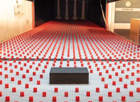
A standard configuration of the objects used for representing atmospheric flow can be seen in the following image:
The roughness of the terrain affects the mean velocity profile in the Atmospheric Boundary Layer (ABL). The following image shows this effect:
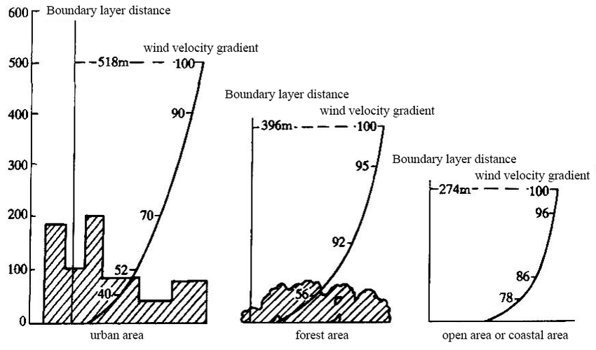
According to Brazilian and European wind standards, the ABL profile can me represented by a roughness factor (\(z_0\)). The objective of this module is to serve as a tool for generating the geometry of the roughness elements, in order to achieve a corresponding ABL profile. The validation of the ABL profile is based on the mean velocity profile and turbulence intensity. This profile is then used to obtain a corresponding roughness factor and compared to the ones presented by the standards.
Usage
There are several ways to use Roughness Elements generation module. The main one is to run as a module, using:
uv run python -m cfdmod.roughness --config {CONFIG_PATH} --output {OUTPUT_PATH}
It takes two arguments: the path for the .yaml configuration file with the generation parameters and the output path for saving the .STL file. For standard use, the user must fullfill a configuration file with the parameters. One example of the configuration is as it follows:
N_elements_x: 10
N_elements_y: 10
element_params:
# Size in Z axis:
height: 10
# Size in Y axis:
width: 10
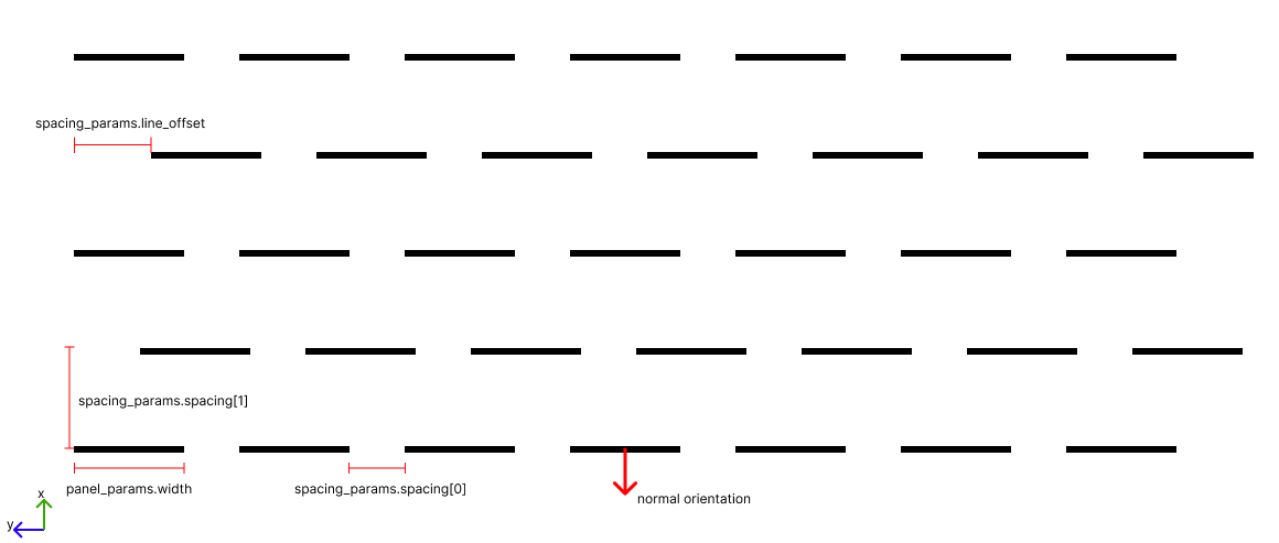
spacing_params:
# Spacing value is defined by the distance between the end of a element
# and the start of another one.
# Spacing indexed by axis (X=0, Y=1)
spacing: [10, 10]
# Line offset is defined by the distance between the the start of a line
# and the start of the first element
line_offset: 10
# Optional, default is y
offset_direction: x
The parameters consist in defining the number of replication in each axis. The figure below shows how the blocks are generated through configuration
Another way is running via notebook.
Positioned roughness elements
One typical application of the roughness elements is to use them to mantain the turbulence near the ground, in the upwind direction. Because of that, their position should follow the terrain profile.
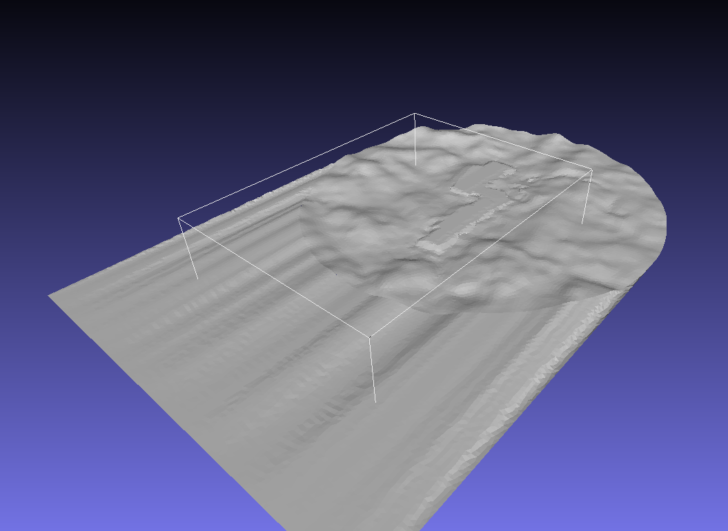
To generate and position the roughness elements following a terrain profile, the user must specify a bounding box to where to spawn roughness elements. The image below illustrates a bounding box that is going to delimit the roughness elements spawn location:
The user can also specify multiple surfaces if the bounding box crosses them. Parameters file must also be an input, such as the following example:
element_params:
  height: 5
  width: 5
spacing_params:
  spacing: [20, 20] # Spacing indexed by axis (X=0, Y=1)
  line_offset: 10
  offset_direction: x # Optional, default is y
bounding_box:
  start: [-500,-1000,0]
  end: [2400,1000,0]
surfaces: # Dictionary of surfaces
  disk: "./fixtures/tests/roughness_gen/disk/disk.lnas"
  loft: "./fixtures/tests/roughness_gen/loft/loft.lnas"
Currently the only way to run this use case is via notebook for positioning elements.
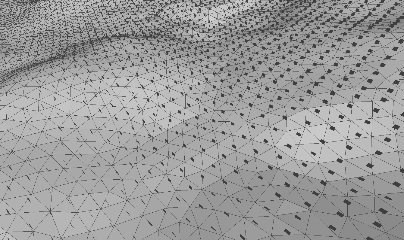
Output
The expected output is a STL file containing the information for creating the geometry. This file can be inspected in CAD softwares, such as mesh lab. An example of the output can be seen below:
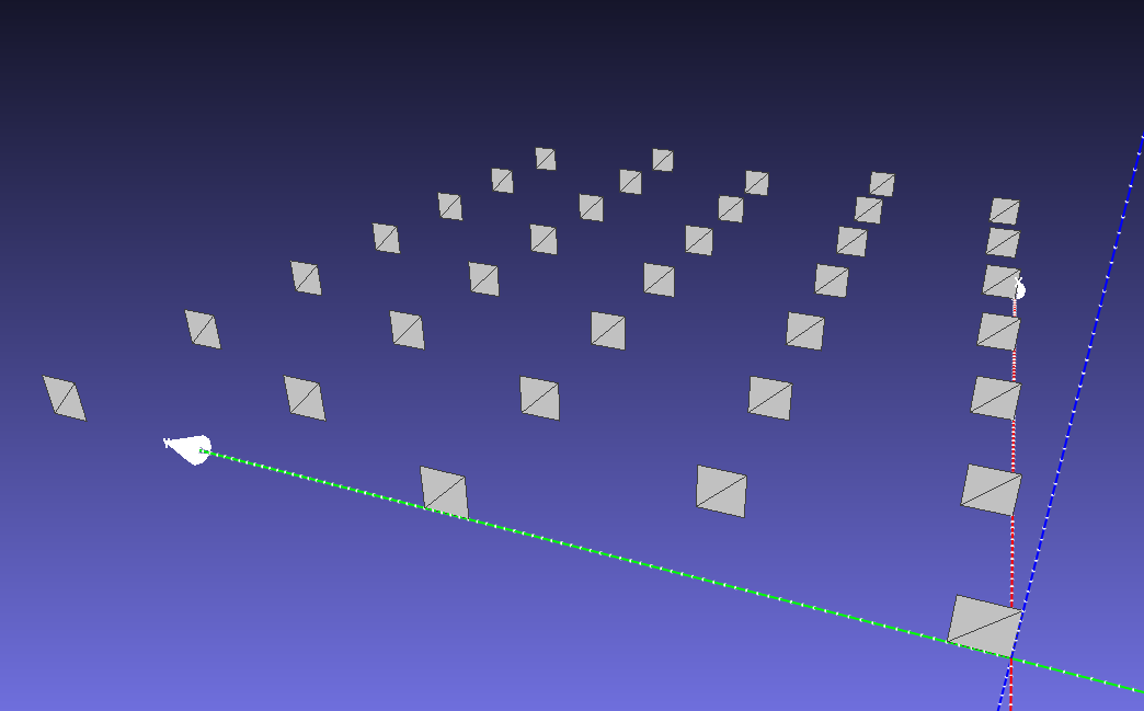
For the second use case, generating elements that conform to the terrain surface, the output geometry will be: