Geometry Preparation
AeroSim uses the Immersed Boundary Method (IBM) to represent solid bodies in the simulation. Geometries are provided as STL files and are not used to generate a volume mesh - the surface is instead sampled directly into a set of IBM points. As a result, geometry requirements for AeroSim are fundamentally different from those of FVM-based solvers.
See also
For a deeper explanation of how geometries work, how triangles are refined, and how IBM points are placed, see the Geometry Discretization reference.
What actually matters: triangle quality
The IBM places one Lagrangian point at the centroid of each triangle. The distance between these points should be approximately uniform and close to one lattice unit at the desired resolution. This is achieved when triangles are as close to equilateral as possible - all three edges of similar length.
When triangles are elongated, obtuse, or highly irregular, the resulting IBM points are unevenly spaced. This introduces errors in the force interpolation between the fluid grid and the body surface, which degrades the accuracy of geometry representation.
Important
The most important quality criterion is: triangles should be as equilateral as possible.
Warning
Duplicate faces do matter: each triangle produces one IBM node, so duplicated triangles place two nodes at the same position, doubling the local force and corrupting the boundary condition. Duplicates should be removed before importing the geometry.

Good: edges of similar length, IBM points evenly spaced.¶ |

Poor: elongated shape leads to uneven IBM point distribution.¶ |
Note
Unlike FVM solvers, AeroSim does not require watertight geometry or manifold topology. Open surfaces, small holes, and edges shared by more or fewer than two triangles do not cause any issues. You do not need to spend time closing holes or repairing topology - the focus should be on triangle shape.
Preparing the geometry in MeshLab
MeshLab (free, open-source) is the recommended tool for inspecting and fixing geometry before importing into AeroSim. The steps below cover the most common operations and should be applied as a standard checklist regardless of the geometry source.
Important
These filters should be applied to every geometry as a baseline before remeshing:
Filters>Cleaning and Repairing>Remove Duplicate Faces- removes faces that share the exact same vertices, which would create overlapping IBM nodes.Filters>Cleaning and Repairing>Remove Duplicate Vertices- merges vertices that occupy the same position.Filters>Cleaning and Repairing>Remove Unreferenced Vertices- removes vertices not connected to any face.
Remeshing to improve quality
Isotropic remeshing replaces the existing triangulation with a new one composed of uniform, near-equilateral triangles. It is the most effective way to prepare a geometry for IBM:
Go to
Filters>Remeshing, Simplification and Reconstruction>Isotropic Explicit Remeshing.Set
Target Lengthto the desired edge length (in meters).Press
Apply.
Note
Since AeroSim automatically refines triangles to the target area at simulation time, the target length does not need to be small. Setting it too small generates a large number of triangles that AeroSim would have produced anyway, increasing file size and import time with no benefit. A coarser target length is fine - the goal of remeshing is to improve triangle shape, not to control size.
The exception is when exporting surface data using body-based output. In that case, the original triangle size determines the resolution of the exported data, since AeroSim maps results back to the input geometry triangles. See for details.
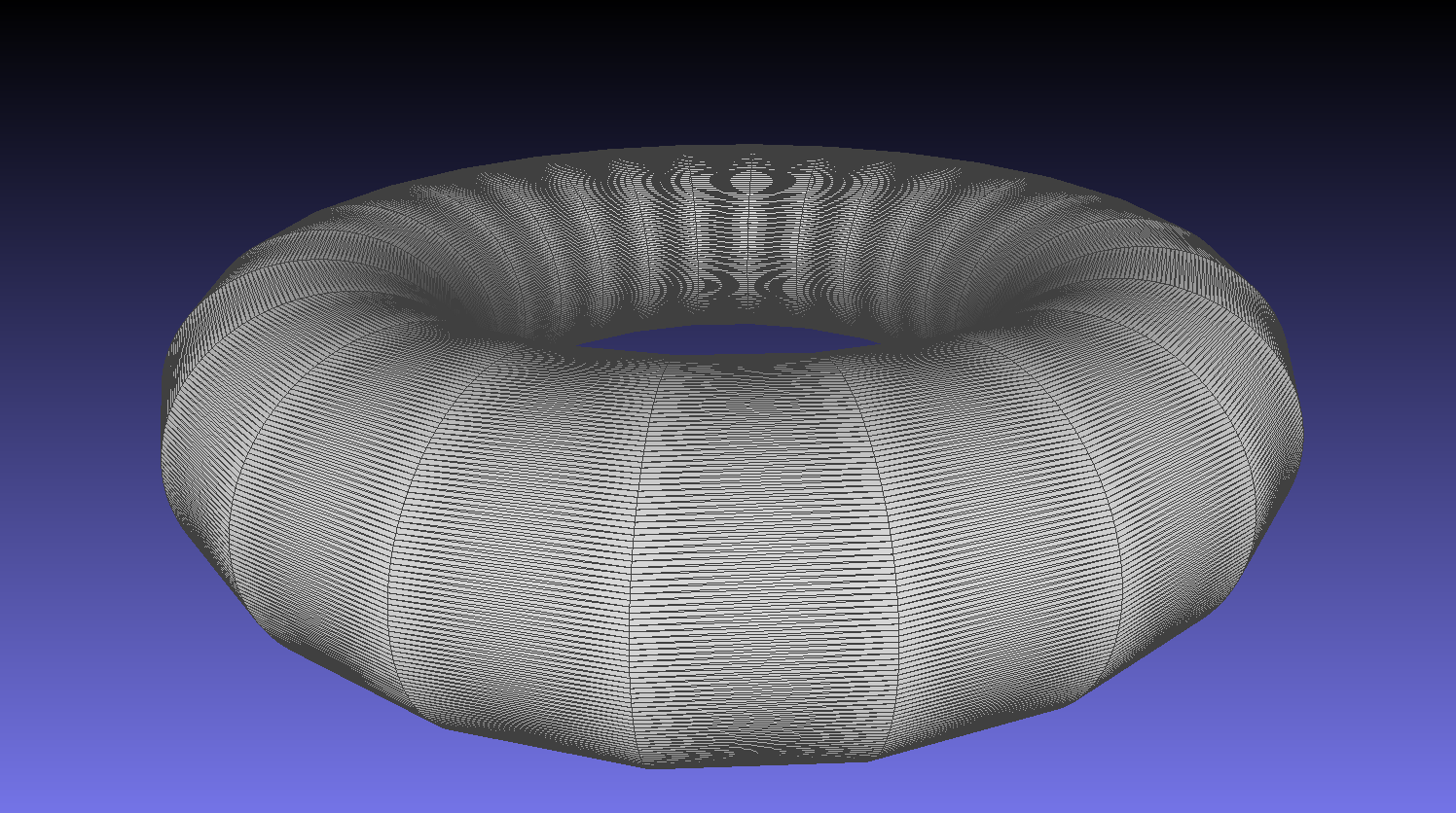
Before: elongated, low-quality triangles.¶ |
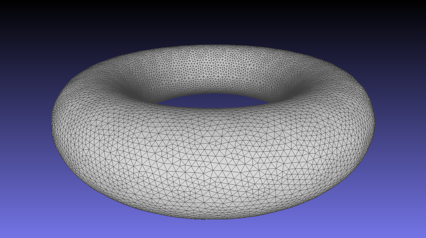
After: uniform, equilateral triangles after isotropic remeshing.¶ |
Note
If a specific region requires finer IBM resolution (e.g. sharp building edges, facade details), that region should use a smaller target length matching the local refinement level. Transitions between coarse and fine triangle regions are acceptable.
Inspecting specific regions
If only certain parts of the geometry are suspected to have quality issues, or for more detailed troubleshooting, MeshLab can highlight problematic faces directly:
Go to
Filters>Selection>Select 'problematic' faces.Enable
Select by Aspect Ratioand pressApply.Problematic triangles will be highlighted in the viewport.
Tip
With the selection active, enable Remesh only selected faces in the isotropic remeshing dialog to restrict the operation to those regions only.