
 AeroSim Docs
1. Geometries
The first thing to do before setting up a simulation is to bring in the geometries we will work with. Here we will create the built-in geometries needed to run an ABL simulation.
Adding the plane
Start by creating a plane: go to Add Geometry -> Generate Primitive, then select Plane in the form.
The plane size we will use is 8000 m in X and 2000 m in Y (streamwise is X, height is Z, spanwise is Y).
The plane can be moved before or after generation. We will translate it by 2000 m in X, because we usually want a longer fetch downstream than upstream.
After that we should have our first geometry, as in the screen below.
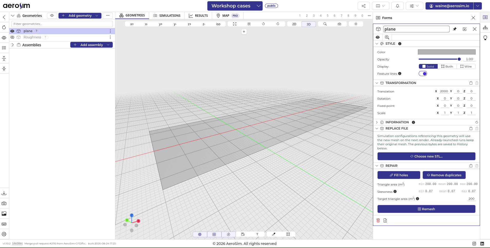
The generated plane, positioned in the domain.
Adding roughness elements
To generate the inflow profile of the ABL, AeroSim uses roughness elements along with a wall model on the plane, which keeps the profile and the turbulence intensity as the flow develops.
This is similar to what a wind tunnel does with the blocks placed upstream of the model: the flow enters near-uniform, develops over the fetch of blocks, and reaches the model with the profile and the turbulence we want.
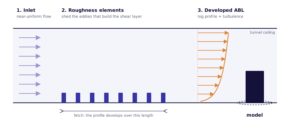
Roughness elements upstream of the model in a wind tunnel test section.
To add them, use Add Geometry -> Create Roughness Elements and then choose the parameters. For this case we will use a CAT 2 profile, so the catalogued AeroSim roughness elements for CAT 2 will be used.
The parameters can be tweaked for tests. The default values are the ones AeroSim has used and validated internally for each category.
Both Linear and Radial roughness elements can be generated, the radial ones being arranged as a circular table for 360-degree cases.
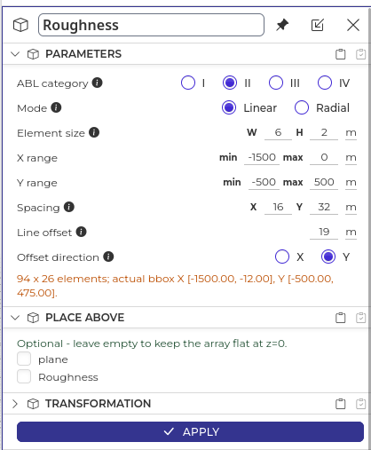
The roughness elements form, with the CAT 2 parameters.
With all this done, our geometries are set up.
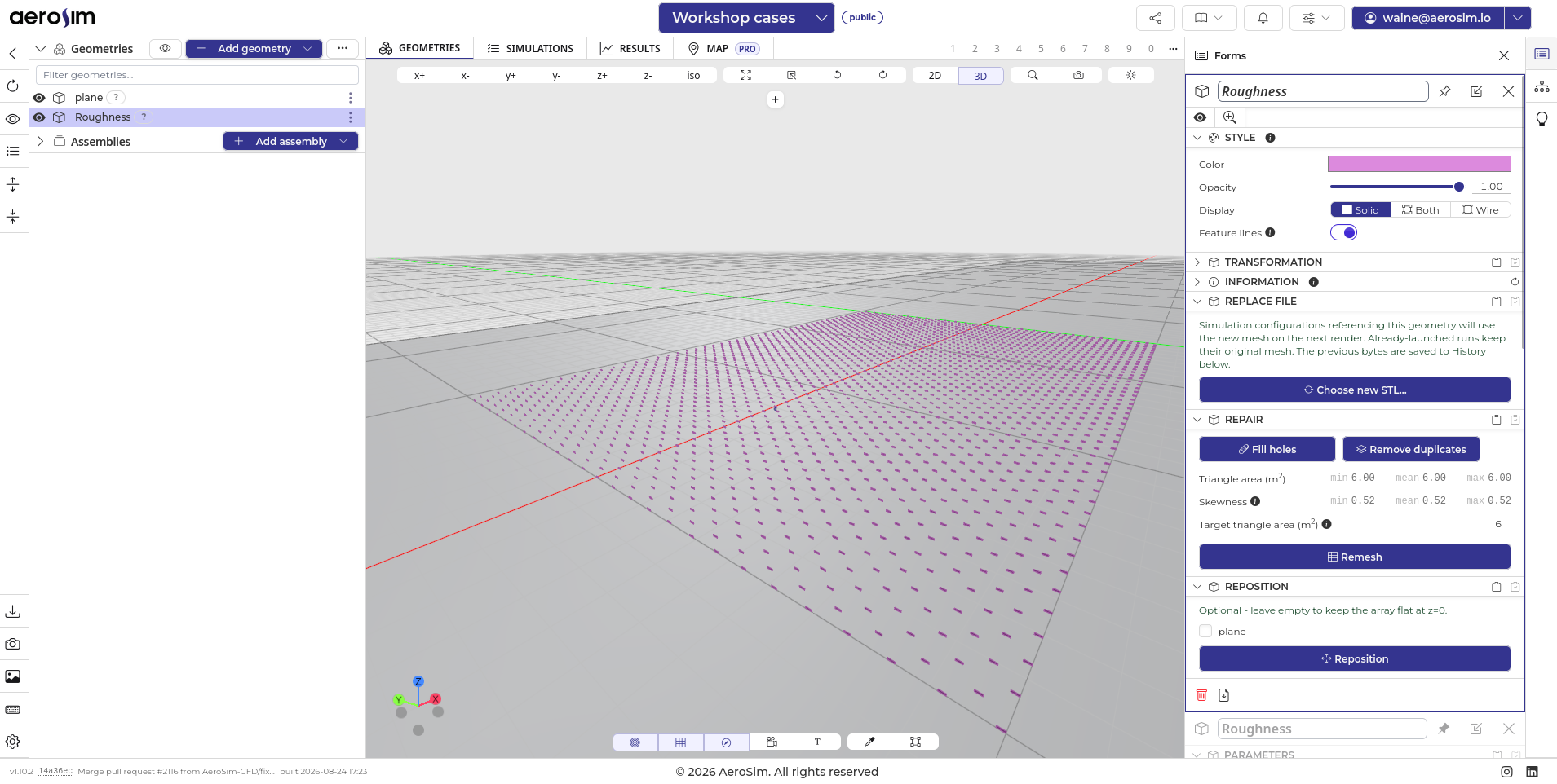
Plane and roughness elements, ready for the simulation setup.
Next steps
With the geometries generated, we can move on to creating the simulation.