
 AeroSim Docs
2. Simulation
With the geometries generated, we can create the simulation itself and attach them to it with their boundary conditions.
Creating the simulation
Now we go to the Simulations tab and create a new simulation, which we will call
ABL Cat2. With this we can start setting up the configurations.
Geometries and their boundary conditions
After creating the simulation we need to add the geometries to it. We will add both the plane and the roughness elements.
When adding a geometry, we need to set its boundary condition. By default it is no-slip. For the roughness elements, we keep the no-slip BC. For the plane, because this is an ABL case, we set its BC to ABL Wall Model and the roughness length to that of the category we are interested in, which for CAT 2 is 0.05 m.
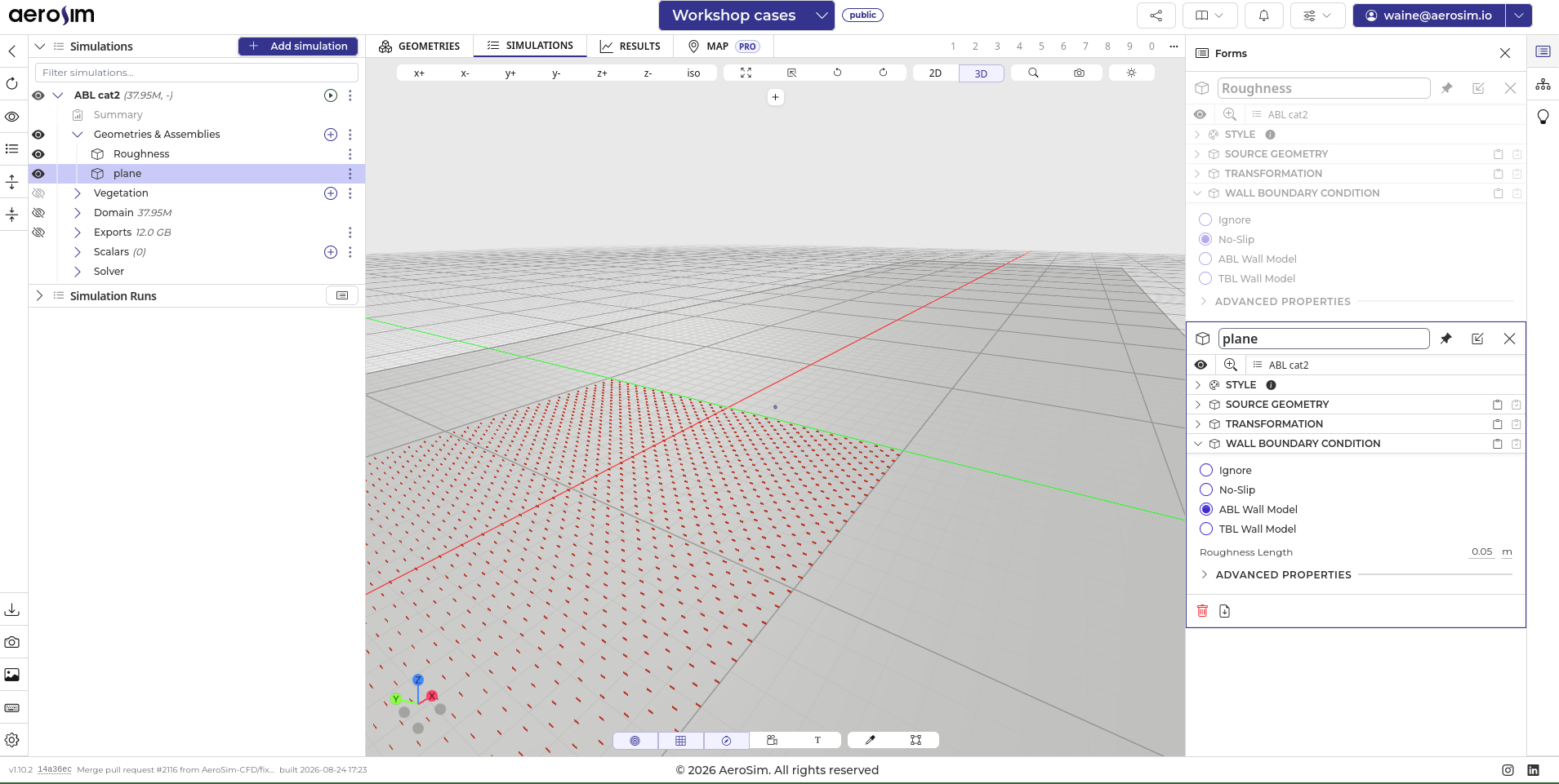
Plane and roughness elements added to the simulation, each with its boundary condition.
Next steps
With the simulation created and the geometries attached, we can move on to the mesh setup.