
 AeroSim Docs
3. Mesh
For the mesh setup in AeroSim, we need to define the domain limits, add the refinements we need and set the baseline resolution. After that we can check the mesh and iterate on it.
Domain
After adding the geometries and their BCs, we move on to the domain setup, starting with the domain limits. The values we recommend overall are 7000 m for X, 1500 m for Y and 850 m for Z. These values can be increased or decreased depending on blockage and area of interest, but we don’t recommend going with a much smaller domain.
There is also the domain translation, which in X we use for the development length, and in Z, for numerical reasons, we keep as -50.1 m by default (the .1 avoids issues with block transition positions).
For the development length we will use 1500 m. This can be tweaked for building height and ABL development, but we don’t recommend less than 150 times the baseline resolution, because the profile may not be fully developed before it.
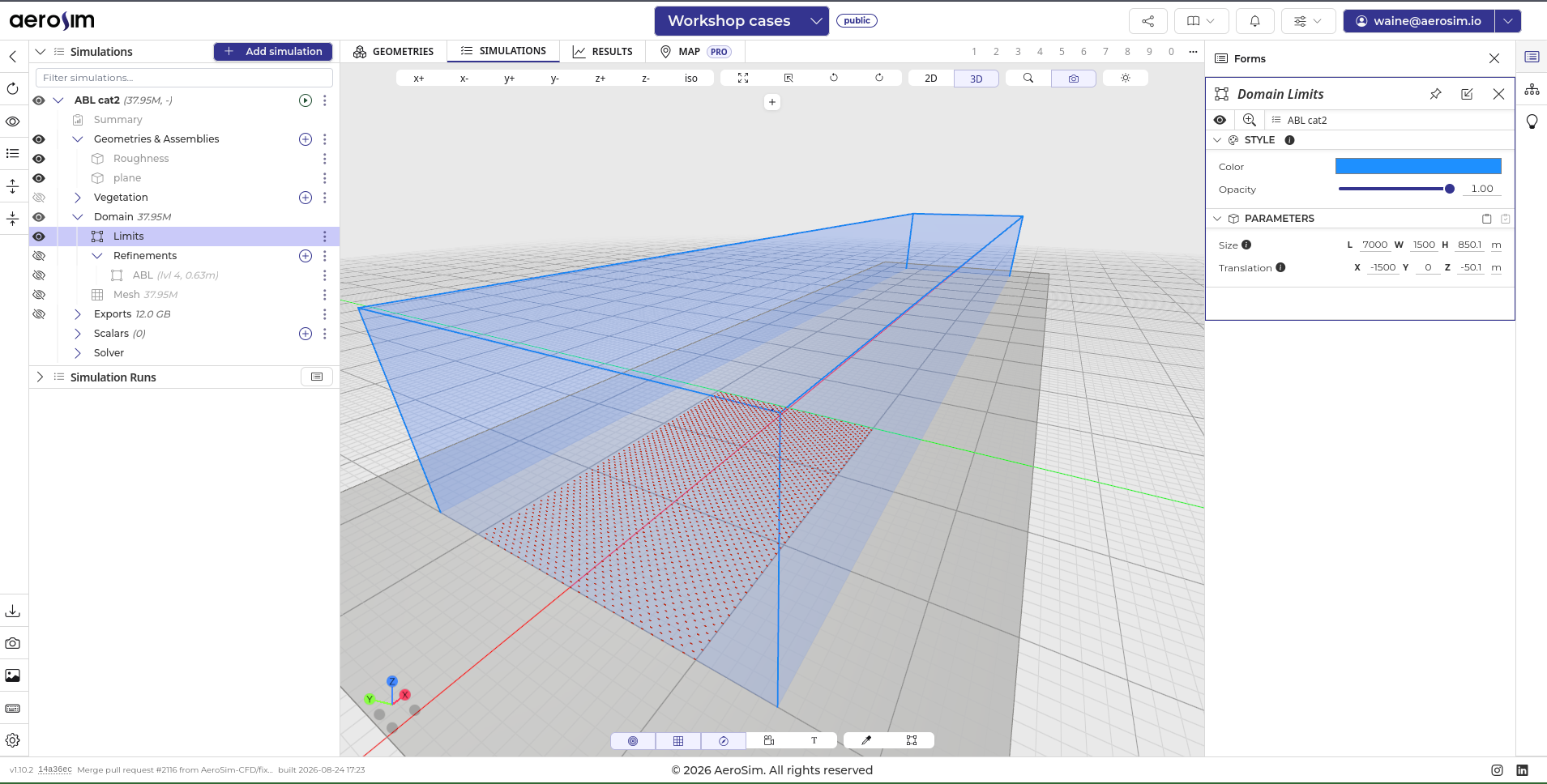
Domain limits and translation for the ABL case.
Refinements
The domain starts at a baseline resolution (by default 10 m). For the ABL, the refinement used internally by AeroSim is between 1.2 m and 1.6 m, for good ABL development and results. For this we add an ABL refinement to the case.
AeroSim uses a 2:1 refinement, so each level halves the cell size. Starting from the default 10 m baseline, the progression is 10 m -> 5 m -> 2.5 m -> 1.25 m, which reaches the ABL refinement we want in three levels.
This progression is only an example. The reachable cell sizes are always the baseline halved repeatedly, so changing the baseline moves the whole ladder: a 12 m baseline gives 12 m -> 6 m -> 3 m -> 1.5 m instead. That is why we set a target and a maximum rather than a single value, and why we can iterate on the baseline later without touching the refinement boxes.
For its parameters, we set the unit as meters, the target to 1.5 m and the maximum to 2 m (this gives a broader range of tests for the baseline resolution).
The refinement will be a box starting at the inlet and extending to downstream of the future object we are interested in. It is very important that it starts from the inlet, otherwise numerical diffusivity may greatly affect the results.
In X we will use -1500 m to 200 m, in Y from -100 m to 100 m, and in Z from -2 m to 50 m. These values greatly depend on the object we will add to the simulation later, and can be increased or decreased depending on it.
We also need to set the margin, to make sure the transition between levels is smooth and to avoid abrupt jumps in the domain that may generate numerical effects. The recommended values are X+ = 50, Y+ = Y- = Z+ = 30, X- = Z- = 0.
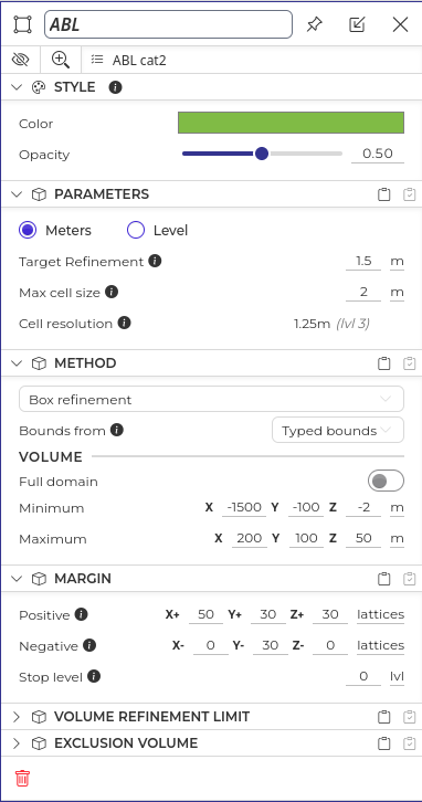
The ABL refinement form, with the target resolution, the box extents and the margins.
After this, we should have our refinement set up and the domain should look like this.
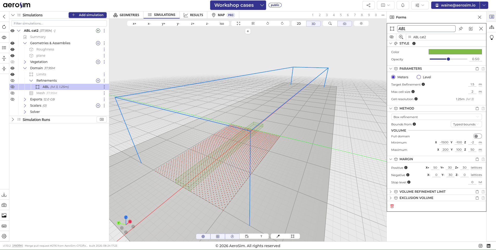
The refinement box in the domain, starting at the inlet.
Generating the mesh
After all this we can check the mesh. The AeroSim mesh is based on blocks, each block being 8 nodes per edge.
We first define a baseline resolution, which by default is 10 m. With that we can refresh the mesh and check the number of nodes, in total and per level. The mesh generation should take less than a minute.
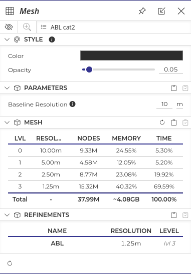
The mesh form, with the baseline resolution and the resulting node count per level.
For this case, the mesh size is ~38M nodes, which is a relatively small mesh for the AeroSim solver.
We can also view the mesh by toggling its eye icon. With that we can check the blocks, their real transitions and the refinements, debug the mesh and iterate over it.
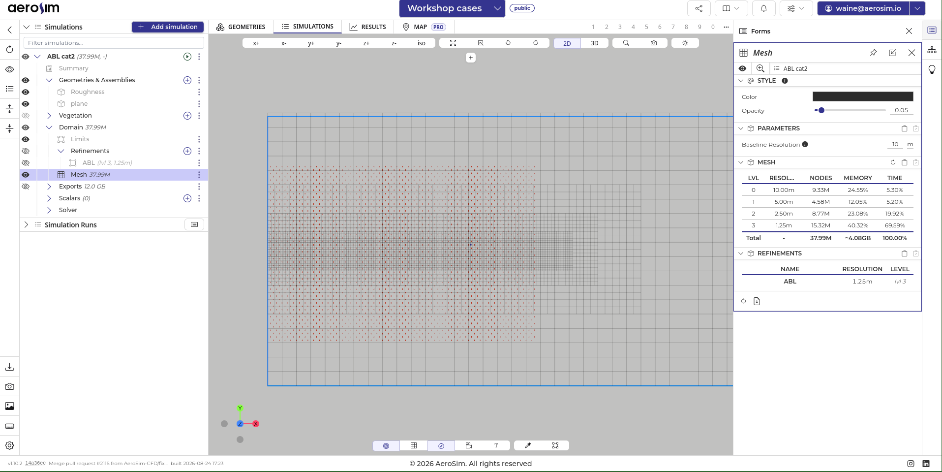
The generated blocks, showing the refinement levels and their transitions.
See also
Mesh covers the block structure, the 2:1 refinement rule and what each extra level costs.
Next steps
Now that our mesh is done, we can follow up to the solver setup.