
 AeroSim Docs
Combine and Spread
Two quantities have to move between the solid (Lagrangian) points and the fluid (Eulerian) lattice every time step: the fluid velocity at the wall must be combined from the surrounding fluid nodes so that the slip can be measured, and the correction force must be spread back to those same nodes so that the slip can be cancelled. Because a Lagrangian point almost never coincides with a lattice node, both operations are interpolations, and the interpolation kernel is the heart of the diffuse-interface method.
Why a regularized delta
In the continuous formulation, transfer between a point on the surface and the surrounding fluid is performed by the Dirac delta \(\delta\), which samples the field exactly at the point. On a discrete lattice the Dirac delta is unusable: a true spike sees only the value at one location and, since no node lies on the surface, that value does not exist. Worse, a nearest-node approximation would make the transferred force jump discontinuously as the point drifts from one cell to the next, which injects spurious noise into the flow.
The solution is to replace the delta with a regularized (smoothed) delta \(D_h\) of finite width, built as a product of one-dimensional kernels \(\phi\):
Peskin[1]. The shape of \(\phi\) is not free. To make the discrete transfer behave like the continuous one, \(\phi\) is required to satisfy a set of moment conditions Roma et al.[2]:
Partition of unity (zeroth moment): the weights must sum to one for any position of the Lagrangian point relative to the grid,
(2)¶\[ \sum_{\mathrm{nodes}} \phi(r) = 1 . \]This guarantees that combining a constant velocity field returns that same constant, and that spreading a force conserves its total magnitude regardless of where the point sits between nodes.
First moment: the weights must reproduce a linear field,
(3)¶\[ \sum_{\mathrm{nodes}} r\,\phi(r) = 0 . \]This makes the interpolation exact to first order, so the transferred quantity does not develop a position-dependent bias as the point moves through a cell.
A kernel that meets these conditions transfers momentum smoothly and consistently as bodies and grid shift relative to one another, which is precisely what a robust no-slip enforcement needs.
The number of grid nodes the kernel touches in each direction is a design choice that trades accuracy, smoothness, and cost. A wider support distributes the force over more nodes, which makes the transfer smoother and lets the kernel satisfy more moment conditions (higher formal accuracy), but it also thickens the diffuse band, blurs the wall further, and raises the cost since every Lagrangian point now reads from and writes to more nodes. Nassu supports three widths and lets the application pick the balance:
Support |
Half-width |
Character |
|---|---|---|
|
\(\pm 1.0\) |
Narrowest band, cheapest, sharpest wall. |
|
\(\pm 1.5\) |
Intermediate smoothness and cost; the production default. |
|
\(\pm 2.0\) |
Smoothest transfer at the highest cost and the widest band. |
The default is the smoothed three-point kernel of Yang et al.[3], whose three-grid-cell support is the smallest that still satisfies the zeroth and first moment conditions above while keeping a continuous derivative across its pieces.
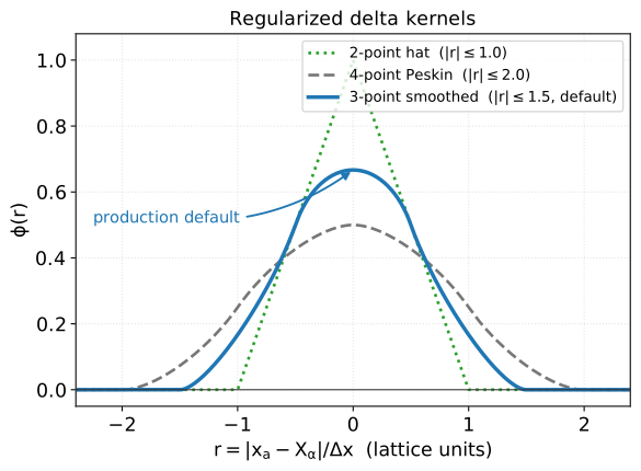
Regularized delta kernels \(\phi(r)\) for the supported support widths. Wider kernels trade a sharper interface for a smoother force spread; the 3-point smoothed kernel (production default) is the narrowest that still satisfies the zeroth- and first-moment conditions.
Choosing the support width
Start from 3_points, the production default. Drop to 2_points when a sharper wall and lower cost outweigh smoothness, as on well-resolved geometries. Move to 4_points when the transfer must be as smooth as possible and the wider band and extra node accesses are acceptable.
Combine: measuring the slip
The IBM is then applied as follows. The flow velocity on the solid node has to be interpolated from the fluid nodes:
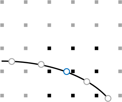
where the values from black grid nodes are interpolated in the blue mesh points.
Note
This interpolated density is employed only in the force calculations and isn’t used for the estimation of pressure at the solid body surface, since it also counts nodes internal to the Lagrangian mesh.
where \(r_{\alpha}=(x_{\alpha}-X_{\alpha})/\Delta x\) for \(\alpha \in \{x,y,z\}\) is the signed per-component separation between the fluid node \(x_{\alpha}\) and the Lagrangian point \(X_{\alpha}\) in grid units, and \(\phi\) is the smoothed delta function, which depends only on \(|r_{\alpha}|\). The production default is the smoothed three-point kernel of Yang et al.[3], with support \(|r| \leq 1.5\):
The two narrower widths follow the same moment-condition philosophy. The 2_points support is the linear hat \(\phi(r) = 1 - |r|\) for \(|r| \leq 1\) (zero otherwise); it is the cheapest and sharpest, but only satisfies the zeroth-moment (partition-of-unity) condition. The 4_points support is the four-point kernel of Peskin[1],
Direct forcing: no-slip as feedback
With the interpolated velocity in hand, the method has to decide what force will pin the fluid to the wall. The original immersed boundary method of Peskin[1] answered this with an elastic analogy, treating the boundary as a spring and deriving the force from its deformation. That works for flexible membranes, but for a rigid body it leaves the wall velocity only approximately enforced and ties the stable time step to an artificial stiffness.
Nassu uses the direct-forcing descendant of that idea Uhlmann[4]: rather than model a spring, compute directly the force that, applied over one step, drives the interpolated velocity to the prescribed wall value. This turns no-slip enforcement into a simple feedback loop, where the slip that remains at the boundary is fed back as the force needed to remove it:
where \(k\) is the sub time-step. Read the correction term as a target minus actual error: when the interpolated velocity \(u_{\alpha,k}^{\mathrm{interp}}\) already matches the wall velocity \(u_{\alpha,k}^{\mathrm{target}}\) the bracket vanishes and the force stops changing, so the loop has converged; any residual slip produces a force in the direction that cancels it. The factor \(\rho_{k}^{\mathrm{interp}}/\Delta t\) converts that velocity error into the momentum-per-step that has to be injected, consistent with the Guo forcing used by the collision step. The leading factor \(2.0\) is the Guo half-step coefficient: under the Guo-corrected velocity a force increment \(\Delta f\) shifts the velocity by only \((\Delta t / 2\rho)\,\Delta f\), so cancelling a residual slip \(\Delta u\) in one step requires \(\Delta f = (2\rho/\Delta t)\,\Delta u\), which is exactly the correction applied here.
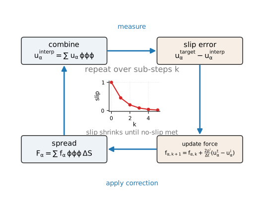
Direct-forcing feedback loop. The residual slip at each Lagrangian point drives the next force correction; spreading that force and re-combining shrinks the slip over the iterations \(k\) until the no-slip target is met.
The force \(f_{\alpha,0}\) and the target velocity on a solid node are null. From past experiences, only one iteration is sufficient to give a good accuracy when using the force from the last time step as initial value. The reason is that the flow changes little between consecutive steps, so last step’s force is already an excellent first guess and a single correction closes most of the remaining gap. However, for high Reynolds LES simulations, it might be necessary to enforce more than one iteration to assure that there will be no fluid penetration. At high Reynolds number the near-wall velocity is large and steep, so a single pass can leave enough residual slip for fluid to leak through the surface; repeating (7) for a few sub-steps \(k\) drives that residual down before the force is committed to the collision.
Spread: returning the force
Finally, the IB forces are spread to the fluid nodes. These forces are inputted into the same neighbouring fluid nodes used for velocity and density interpolation:
Using the same kernel \(\phi\) for the combine and the spread is not a convenience; it is what keeps the exchange conservative. Because the kernel satisfies the partition of unity (2), the total force handed to the fluid in (8) equals the force computed on the solid point, so no spurious momentum is created or lost in the transfer.
The weight \(\Delta S\) is the surface area carried by the solid node, the patch of wall each Lagrangian point represents. It converts the per-area force density at the point into the force actually spread to the lattice, so a point that stands for a larger piece of surface injects proportionally more momentum. In general, it can be assumed that \(\Delta S = A/N\), with \(A\) being the total surface area of the object and \(N\) the total number of IB nodes. However, the current solver adopts a more robust definition for the element area: rather than averaging the whole surface over all points, it assigns each Lagrangian point the area of the triangle it sits on, which keeps the spread accurate when the triangulation is uneven. How that per-element area is computed is detailed in the solid mesh section.
The force field generated in Eulerian grid is computed in LBM evolution equation and gives a satisfactory representation of a solid body immersed in fluid flow.
Note
When the IBM is used along with multiblock, the area applied to spreading equation is relative to the grid in which the Lagrangian node is located. The area of an element located in lvl 1 will be four times its area if it was being measured relative to lvl 0.
Canopy drag is not an IBM mode
Use the volumetric region, not IBM
Canopy / vegetation drag is not modelled through the IBM in Nassu. A vegetation canopy is a distributed momentum sink spread through a volume, not a surface to enforce no-slip on, so it is configured as a volumetric porous region rather than as an immersed body. That region applies a quadratic (Forchheimer / canopy) drag force \(F_\alpha = -\beta\,|u|\,u_\alpha\) on every fluid node it covers, which is the same speed-squared dependence a leaf-area-density model produces.
A canopy drag of the leaf-area-density (LAD) form,
with drag coefficient \(C_{\mathrm{D}}\) and leaf area density \(\mathrm{LAD}\) in \(\mathrm{m}^{2}/\mathrm{m}^{3}\) Kang et al.[5], is quadratic in the local velocity. It maps directly onto the volumetric quadratic sink \(F_\alpha = -\beta\,|u|\,u_\alpha\) by setting \(\beta = \tfrac{1}{2}C_{\mathrm{D}}\,\mathrm{LAD}\) (lattice units), so the canopy is configured through models.volumetric_regions (porous_beta) and the IBM is left for genuine solid surfaces. See the porous-media theory page for the full force balance.