
 AeroSim Docs
Wall Model - IBM
This is the second of the two coupling routes introduced on the LBM boundary-condition page. Use it when the solid surface is an immersed STL body that does not align with the Cartesian lattice, which is the common case in CWE: the curved roofs, inclined facades and sharp edges of buildings and vehicles. The wall function is the same as for the boundary-condition route; the difference is that here the modeled stress is applied as a velocity correction, spread back to the fluid through the immersed-boundary interpolation rather than written directly into a wall-node tensor.
To couple the wall model to fluid flow simulation, the immersed boundary method (IBM) operates with a velocity correction calculated from the selected wall function.
From the Lagrangian mesh, some auxiliary points must be defined as illustrated below ( Shi et al.[1], Du et al.[2], Wang et al.[3]):
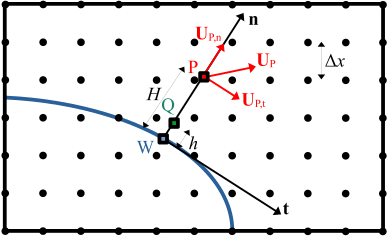
where the point P is the reference point \(\mathrm{P_{N}}\) at normal direction in which the velocity will be linearly interpolated from nearest points. It is usual to fix a distance \(H\) of at least \(3\Delta x\) from the wall, which will be located in a point external to IBM diffusive layer.
A subtle trap: keep the reference point outside the diffusive layer
P must sit beyond the IBM diffusive layer, where the velocity field is already free of the spreading kernel’s smoothing. Sampling P inside that layer reads a velocity the immersed-boundary forcing has artificially damped, so the wall function is fed a corrupted matching-point state. The \(H \geq 3\Delta x\) rule of thumb places P clear of the layer.
This velocity profile between P and the wall is modeled and the velocity at Q is calculated. The distance from W to Q is usually fixed \(h=0.1 - 0.25\Delta x\).
The point Q is also distanced from the wall towards normal direction and is an auxiliary point where a calculated velocity will be imposed. The correction will be applied using an interpolation-spread procedure from IBM at Q point.
Activate the wall model only after the flow has settled
Let the simulation reach a stable flow with the standard IBM before switching on the wall model. Once activated, the wall model replaces the standard IBM, which ceases execution. Enabling it on a transient start-up field feeds the wall function an unconverged matching-point state.
Hence the algorithm for the WM-IB-LBM executes the following sequence of operations:
Reference velocity \(\mathbf{u}\) is interpolated at P using a linear interpolation between nearest nodes and decomposed in its tangential \(t\) and normal \(n\) components with:
The magnitude of \(\mathbf{u}_{t}\) is then assumed as \(u_{\mathrm{t,P_{N}}}\) and replaced in the wall function for the calculation of tangential velocity at Q. Concretely, for the log-law closure the friction velocity is recovered from the matching-point tangential velocity via (2),
and the tangential velocity at the near-wall point Q follows from evaluating the log law (1) at \(z_{\mathrm{Q}}\):
The magnitude from \(u_{\mathrm{t,Q}}\) is multiplied by the unit vector \(\mathbf{u}_{t}/ |\mathbf{u}_{t}|\) to obtain \(\mathbf{u}_{\mathrm{t,Q}}\)
The normal velocity at Q is given by a quadratic relation (Du et al.[2]):
Then, the target velocity at Q is given by \(\mathbf{u}_{\mathrm{Q}}=\mathbf{u}_{\mathrm{t,Q}}+\mathbf{u}_{\mathrm{n,Q}}\).
The velocity correction is implemented using a traditional interpolation-spread procedure from Q.