
 AeroSim Docs
Wall Model
LES simulations usually present low resolution near wall boundaries, resulting in a poor representation of the turbulent boundary layer. The use of turbulent models to describe the flow near wall can provide more accurate values of wall stresses at boundary positions, hence wall models are adopted in turbulent flow Large-eddy simulations with a high \(\Delta y^{+}\).
Why a wall model?
In a turbulent boundary layer the velocity does not approach the wall smoothly. The flow organises itself into thin, energetic structures (streaks and quasi-streamwise vortices) whose size shrinks as you get closer to the surface. These near-wall structures carry most of the turbulent shear stress, and their characteristic width is measured in viscous (wall) units, \(y^{+}=y\,u^{*}/\nu\), where \(u^{*}\) is the friction velocity and \(\nu\) the kinematic viscosity (Pope[1]).
A wall-resolved LES has to place several grid cells across these structures, which means the first fluid cell must sit at \(y^{+}\approx 1\) and the streamwise and spanwise spacings must also be a handful of wall units. Here is the difficulty: wall units shrink as the Reynolds number grows. The number of grid points required to resolve the near-wall layer therefore scales almost linearly with Reynolds number, close to \(Re^{1.8}\) to \(Re^{2}\) for the wall region (Choi and Moin[2]). At the Reynolds numbers of full-scale engineering, routinely \(10^{6}\) to \(10^{8}\) (in computational wind engineering, for instance, based on building height), wall-resolved LES is prohibitively expensive: the cell count needed to resolve every solid surface would dwarf the rest of the domain.
Key idea: reconstruct the near-wall layer, do not resolve it
Wall-resolved LES cost scales close to \(Re^{1.8}\) to \(Re^{2}\), which makes it unaffordable at full-scale Reynolds numbers. A wall model sidesteps that scaling: instead of resolving the energetic near-wall structures with the grid, it reconstructs them analytically and supplies the wall shear stress directly. The first fluid cell can then sit far above the viscous sublayer while the simulated friction stays correct.
The naive workaround, just using a coarse grid and letting the no-slip wall condition act on the first cell, fails badly. A coarse cell at \(y^{+}\gg 1\) lands deep in the logarithmic region, where the velocity gradient is far gentler than at the wall. Reading the wall stress directly from that gradient underpredicts the friction by a large margin, so the simulated drag, separation points and pressure loads come out wrong. This is the core problem a wall model solves: it lets you place the first cell at a large \(y^{+}\), well above the viscous sublayer, yet still recover the correct wall shear stress (Piomelli and Balaras[3]).
The wall-stress modeling idea
Rather than resolve the near-wall layer, a wall-stress model reconstructs it. The strategy is to take the velocity the LES already computes at a matching point some distance from the wall, assume a known shape for the profile between that point and the surface, and from that shape deduce the wall shear stress that the LES then imposes as a boundary condition (Piomelli and Balaras[3]). The expensive near-wall turbulence is never simulated; it is supplied analytically.
This works because the reconstruction rests on two assumptions that hold well in the inner part of an attached boundary layer:
One-dimensional in the wall-normal direction. Gradients along the wall are negligible compared with gradients normal to it, so the modeled region is treated as a function of the wall-normal coordinate alone.
Quasi-steady. The near-wall layer adjusts to the outer flow much faster than the outer flow itself changes, so at each LES time step the modeled profile is taken to be in instantaneous equilibrium with the matching-point state (Davidson[4]).
These assumptions define a ladder of models of increasing fidelity, and Nassu climbs it page by page:
The logarithmic law of the wall is the simplest rung: a single algebraic profile that fixes the wall stress from one matching-point velocity. It is exact only for an attached, zero-pressure-gradient, equilibrium boundary layer, and it is also the natural way to encode atmospheric terrain roughness for CWE.
The equilibrium thin-boundary-layer (TBL) model keeps the one-dimensional assumption but solves a wall-normal ordinary differential equation instead of a fixed algebraic law, allowing a more general eddy-viscosity profile.
The non-equilibrium TBL model restores the streamwise pressure-gradient term, which matters precisely where the log law fails: near separation, reattachment and the windward and leeward corners of bluff bodies that dominate CWE loads (Piomelli[5]).
Where the assumptions break, accuracy degrades gracefully rather than catastrophically, which is why wall-modeled LES is the standard approach for high-Reynolds CWE (Kawai and Larsson[6]).
Which rung to pick
The closure choice maps directly to the physics of the surface you are modeling. Use the log law for attached, equilibrium boundary layers and for encoding atmospheric terrain roughness. Step up to the equilibrium TBL model when you need a more general eddy-viscosity profile but the pressure gradient is still mild. Use the non-equilibrium TBL model where the streamwise pressure gradient drives the flow: separation, reattachment, and the windward and leeward corners of bluff bodies that set CWE loads.
Limits of validity
The reconstruction rests on the one-dimensional and quasi-steady assumptions, which hold in the inner part of an attached boundary layer. They weaken under strong adverse pressure gradients and break at separation, reattachment, and sharp bluff-body corners. The log law fails first in those regions; the non-equilibrium TBL model extends the usable range but does not make the assumptions exact.
For a point on a surface, as illustrated below, the wall model bridges the extreme points towards normal direction, and considers a 1D flow respective to normal and tangential velocity coordinates.
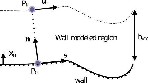
Being \(x^{+}_{n}=x_{n}u^{*}/\nu\) the normal distance from a surface position, the application range of the wall model is parametrized from \(x^{+}_{n,\mathrm{P_{0}}}=0\) to \(x^{+}_{n,\mathrm{P_{N}}}=h_{\mathrm{wm}}^{+}\).
The friction velocity at the wall \(u^{*}\) is defined as:
Calculated using the wall stress from previous time step or directly when the log law approximation is adopted.
Note
Why the lagged stress is enough. An iterative procedure can sharpen the stress estimate, but the small LBM time step keeps the stress magnitude nearly constant over a single step, so reusing the previous step’s value is accurate enough and avoids the per-step iteration.
Application
The particularities that must be adopted for the use of wall models with the LBM boundary conditions and the immersed boundary method are described in separate sections.
Note
The two routes differ only in how the wall stress is handed to the solver, not in the wall model itself. The same wall function feeds both the LBM boundary condition and the immersed boundary method.