
 AeroSim Docs
Turbulence spectra
In a turbulent flow, kinetic energy \(E\) is usually transferred from the largest eddies as they break down into smaller vortices until they reach a critical length to which the viscous dissipation converts this energy into heat. The most common way to visualize this phenomenon is in Fourier space using wave-numbers \(k\) to quantify spatial scales, as illustrated by the energy spectrum in the next section.
The intermediate range between both largest and smallest scales (inertial range) is statistically isotropic. Hence the net energy coming from the energy-containing eddies is in equilibrium with the net energy cascading to smaller eddies, where it is dissipated and the slope of energy spectrum remains constant.
Key idea
Turbulent kinetic energy is injected at the large, geometry-imprinted eddies and cascades down through ever smaller scales until viscosity dissipates it as heat. In the inertial range between the two extremes the cascade is in equilibrium and statistically universal, giving the energy spectrum its constant \(-5/3\) slope. This cascade picture is what tells you which scales an LES must resolve and which it can model.
The three scales of turbulence
The cascade lives between two extremes, and a third scale measures where viscosity starts to matter. Reading a spectrum, or deciding how fine a Nassu mesh has to be, means knowing which of these three scales a given eddy belongs to [1][2].
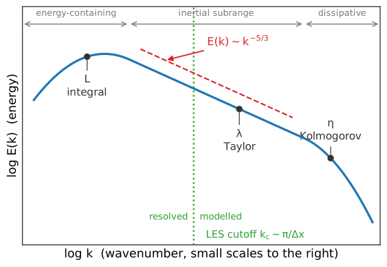
The energy spectrum and the three scales of turbulence. Most energy sits at the integral scale \(L\); the inertial subrange between \(L\) and the Kolmogorov scale \(\eta\) follows the -5/3 slope, with the Taylor microscale \(\lambda\) in between. A well-posed LES places its grid cutoff inside the inertial range.
The integral scale \(L\) is the size of the largest, most energetic eddies. It is set by the geometry of the flow, the body width, the boundary-layer depth, the gap between obstacles, and it carries most of the turbulent kinetic energy. The integral scale is what the inlet condition must reproduce, because getting the big eddies wrong corrupts every smaller scale downstream.
The Kolmogorov microscale \(\eta\) is the smallest eddy, the size at which viscosity finally overwhelms inertia and turns motion into heat. It is fixed by the dissipation rate \(\varepsilon\) and the viscosity \(\nu\):
The separation between the two grows with the Reynolds number as \(L/\eta \sim Re^{3/4}\) [1], which is exactly why resolving every scale (a direct numerical simulation) is hopeless for high-Reynolds flows and why a subgrid model is unavoidable.
The Taylor microscale \(\lambda\) sits between the two. It is not the size of any particular eddy but an intermediate length built from the curvature of the velocity correlation, and it conveniently characterizes the mean strain rate of the fluctuating field; it serves mainly as a reference scale that links the energy-containing range to the dissipative range [1].
The inertial subrange and the -5/3 law
The range of scales between \(L\) and \(\eta\) is the inertial subrange, and it is the most useful part of the spectrum for validation because its shape is universal. Kolmogorov’s argument is that eddies far smaller than \(L\) have forgotten how they were created and far larger than \(\eta\) have not yet felt viscosity, so their statistics can depend only on the wavenumber \(k\) and the rate \(\varepsilon\) at which energy passes through them [3]. Dimensional analysis then forces a single possible form for the energy spectrum:
where \(C_{K} \approx 1.5\) is the (approximately universal) Kolmogorov constant, determined empirically [1]. The slope of -5/3 on a log-log plot is therefore not a fitting result but a prediction for the inertial subrange of any high-Reynolds turbulence, jet, wake, or atmospheric boundary layer alike. This universality is what makes the inertial subrange the gold standard for checking a turbulent simulation: if a Nassu velocity spectrum shows a clean -5/3 band, the resolved energy cascade is physically correct in that range. In Oliveira et al.[4] the inflow velocity spectra are compared directly against the von Karman reference curve, which embeds this same -5/3 inertial decay, to confirm the inlet turbulence is well posed.
Where the LES cutoff should sit
A large-eddy simulation does not resolve the whole cascade; it resolves the energetic large scales and models the rest. The grid (and the LES filter built on it) imposes a cutoff wavenumber \(k_{c}\sim \pi/\Delta x\) beyond which motion is not represented and is instead handled by the subgrid model. The design rule follows directly from the cascade picture: the cutoff should fall inside the inertial subrange, well below the integral scale and well above the dissipative scale [1]. Placed there, the subgrid model only has to drain energy from scales that are already in local equilibrium, which is precisely the regime the Smagorinsky model assumes, and the bulk of the turbulent energy is carried by resolved eddies. If the cutoff is pushed too low, into the energy-containing range, the model is asked to represent eddies that are anisotropic and geometry-dependent, and the result degrades.
Resolve the large scales, model the small ones
Large eddies are anisotropic and carry the imprint of the geometry, so no universal model captures them; they must be resolved. Small eddies are isotropic and statistically universal, so a single subgrid model handles them across every flow. Placing the LES cutoff inside the inertial subrange is what splits the cascade along this line: the resolved side keeps the geometry-specific energy-containing motions, and the modelled side sees only the universal equilibrium scales the Smagorinsky model assumes.
The energy-spectrum plot is the diagnostic for this choice: it shows directly how much of the cascade is resolved and whether the cutoff sits in the universal -5/3 band, which is why it is the primary measure of LES quality.
In LES simulations, the energy spectra plot indicates up to which frequency the flow is being solved. LES models solve explicitly only the larger scales from turbulence spectrum, with small ones being modeled. A comparison between LES and Direct Numerical Solutions (DNS) is illustrated below:
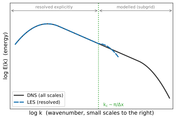
A DNS resolves the whole cascade down to the dissipative roll-off, while an LES follows the same spectrum only up to the grid cutoff \(k_c\) and hands the finer, universal scales to the subgrid model. The cutoff splits the spectrum into a resolved band, computed explicitly and identical for both, and a modelled band carried by the closure.
Turbulence spectra are commonly represented using the Power Spectral Density (PSD) of a probe point. For a discrete time-dependent signal dataset \(x_{n}\left(t_{n}\right)\) sampled at interval \(\Delta t_{s}\), the density-normalized PSD \(S_{xx}\left(f\right)\) is its squared Fourier transform scaled by \(\Delta t_{s}/N\), hence:
where \(f\) is the frequency, \(t_{0}=0\), and \(N\) the number of elements of the dataset. The leading \(\Delta t_{s}/N\) factor is the density normalization that makes Eq. (3) match scipy.signal.periodogram(scaling="density"); dropping the \(\Delta t_{s}\) leaves a periodogram that differs only by the constant sampling-rate factor. The resulting curve can be used to determine the quality of LES modeling since it shows the cutoff frequency of the CFD solution. The signals used for representation of PSD are usually the velocity and the pressure.
Note
In python the raw PSD of Eq. (3) is scipy.signal.periodogram(signal, frequency, scaling="density"). For a converged estimate prefer the segment-averaged scipy.signal.welch, discussed next.
Spectral analysis in practice
A PSD is only as trustworthy as the signal it is computed from, and a few sampling facts decide whether the curve means anything.
The first is the Nyquist limit: a signal sampled every \(\Delta t_{s}\) can represent frequencies only up to \(f_{\mathrm{Nyq}} = 1/(2\,\Delta t_{s})\). Anything faster is not just lost, it is aliased, folded back and added to lower frequencies as spurious energy. For a Nassu probe this means the export interval, not the solver time step, sets the highest meaningful frequency in the spectrum, so the export must be frequent enough that the resolved part of the cascade lies below \(f_{\mathrm{Nyq}}\).
Warning
A subtle trap: aliasing is irreversible
Energy above the Nyquist frequency is not simply lost, it is folded back and added to lower frequencies as spurious energy, and no post-processing separates it again. Set the probe export interval before the run so the resolved cascade falls below \(f_{\mathrm{Nyq}}\); a spectrum sampled too coarsely cannot be repaired afterwards.
The second is frequency resolution and convergence.
A single periodogram from a finite record is a noisy estimate: its variance does not shrink as the record lengthens, it just spreads the same noise over finer frequency bins [1].
The standard approach is to average the spectra of several segments of the record, which trades frequency resolution for a smoother, statistically converged estimate; this is Welch’s method [5], available as scipy.signal.welch.
The longer the total record (in eddy turnover times), the more segments are available and the cleaner the converged spectrum, which mirrors the convergence requirement for any turbulent statistic.
The third is windowing. Cutting a finite segment out of a longer signal is an abrupt truncation that leaks energy across frequencies and corrupts the spectrum, especially the low-frequency, energy-containing end. Multiplying each segment by a smooth taper (a Hann or Hamming window) suppresses this leakage at the cost of a slightly wider effective bin; Welch’s method applies such a window to every segment by default.
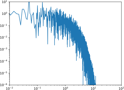
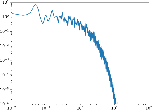
The Gaussian filter below is a complementary, purely cosmetic smoothing applied to an already-computed spectrum to make a short, noisy record legible, it does not add statistical convergence the way segment averaging does. The use of smaller datasets will result in noisy curves. For such curves, a Gaussian filter can be applied to reduce the noise, as illustrated below:
|
|
Two-point correlations and integral length scales
The spectrum tells you how energy is distributed across scales; the two-point correlation tells you how large those scales are in physical space, and it is the quantity that ultimately sets the size of the eddies a Nassu inlet must inject. For a velocity fluctuation it is the normalized covariance between two points separated by a distance \(r\) [1][2]:
where \(\mathbf{e}\) is the unit vector along the separation and the index \(\alpha\) is not summed. The correlation is one at zero separation (a point is perfectly correlated with itself) and decays toward zero as the separation exceeds the size of the eddies that link the two points: nearby points sit inside the same eddy and move together, while distant points belong to independent eddies.
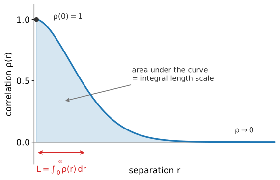
The two-point velocity correlation. It decays from 1 as the separation \(r\) grows, tracking the size of the eddies that link the two points; the area under the normalized curve is the integral length scale \(L\), the size of the energy-carrying eddies.
Integrating this decay defines the integral length scale, the single number that summarizes the size of the energy-containing eddies [1]:
In practice a fixed probe records a time series rather than a spatial field, so the spatial separation is recovered from the temporal one through Taylor’s frozen-turbulence hypothesis, \(r = \bar{u}\,\tau\), which treats the eddies as advected past the probe by the mean flow [2]. This is exactly how Oliveira et al.[4] extracts the integral length scale \(L_{\mathrm{int}}(z)\) from the inflow velocity time series.
The integral length scale closes the loop with the rest of the framework. It is the target that the inflow turbulence must match: the synthetic eddy method sizes its eddies by \(L_{\alpha}\), and the atmospheric boundary layer profile prescribes \(L_{\alpha}(z)\) for each terrain category. Together with the Reynolds stress tensor it constitutes the full second-order statistical specification of a turbulent inlet, the variances and shear stresses say how strong the fluctuations are, the integral length scales say how large they are.